Hello, I would like to learn more about the soft edge blending node in this software.
During my current use, I found that when I calibrate with three projectors, the images cannot overlap accurately. There is always some ghosting and blurring at the overlapping edges.
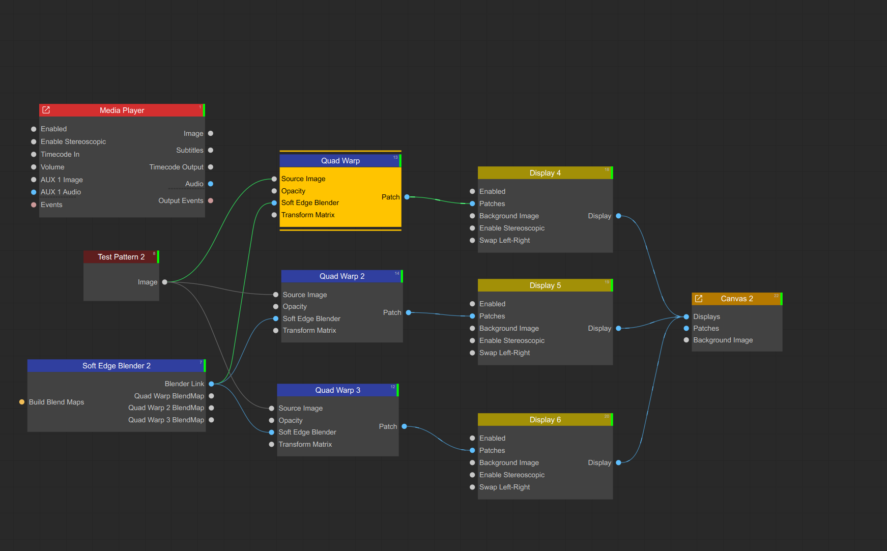
Besides the automatic camera calibration function, are there other features that can achieve precise adjustments? Could you provide a complete node deployment diagram?
For example, if I have six projectors, how should I manually edit the node map and use these functions?
I hope you can help me answer my questions in the form of a video or images.
Manual Calibration of Two or More Projectors on a Panorama Setup
To manually align and blend two or more projectors across a panoramic screen, please follow the steps below:
1. Prepare Your Screen and Calibration Pattern
Measure the physical dimensions of your screen.
For example, if your screen is 10.5 × 4.5 meters, use these exact dimensions in the calibration process.
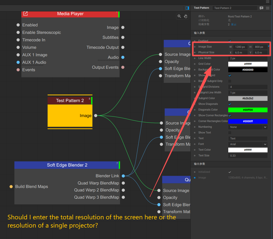
Generate a calibration grid using the Test Pattern node:
Set the Physical Size parameter to match your screen dimensions (e.g., 10.5 × 4.5).
Enable cell numbering to easily identify corresponding cells across overlapping projector regions.
2. Add Physical Markers for Reference
Apply painter’s tape every 1 meter along the bottom edge of the screen.
Draw a black vertical line precisely at each 1-meter mark.
These will act as physical reference points during the UV alignment process.
3. Position Projectors
Arrange the projectors with approximately 15–25% image overlap between adjacent projections.
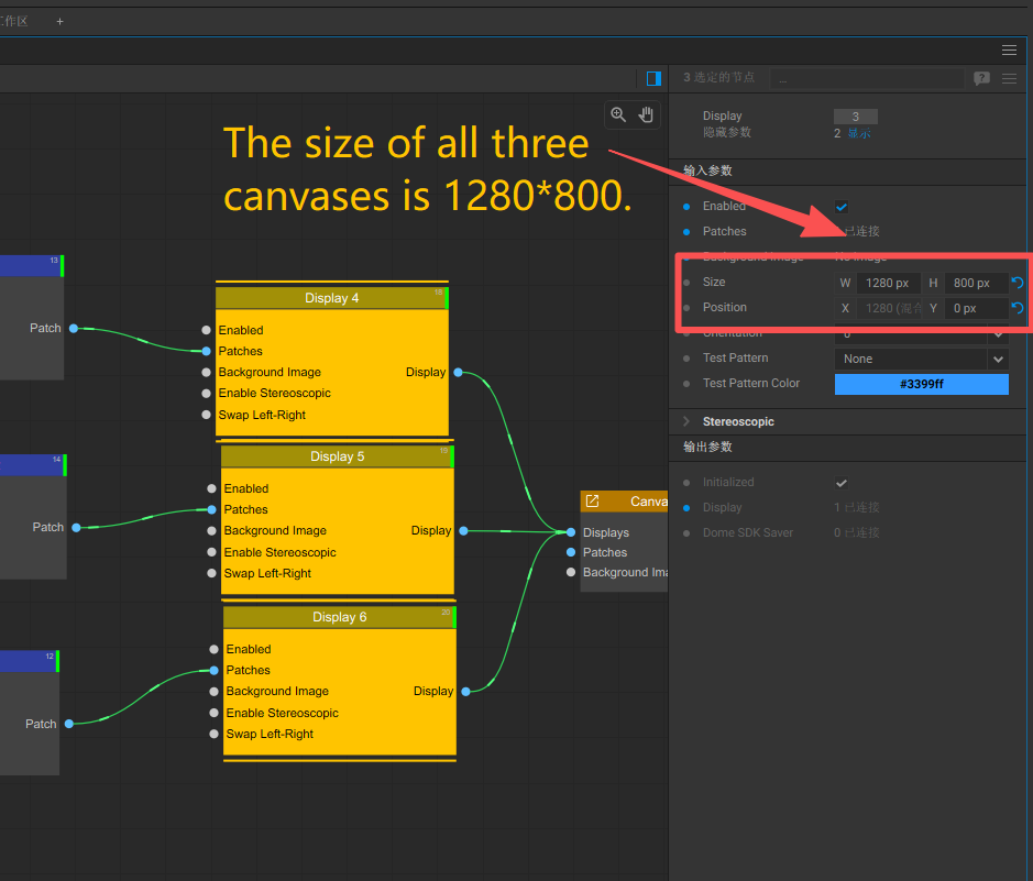
4. Configure Node Graph
Set up your node graph according to your system layout.
If using short-throw projectors or working with a non-flat screen, use the Bezier Warp node:
Enable Perspective Warp within its parameters to allow both linear (perspective) and non-linear transformations.
5. Patch Configuration
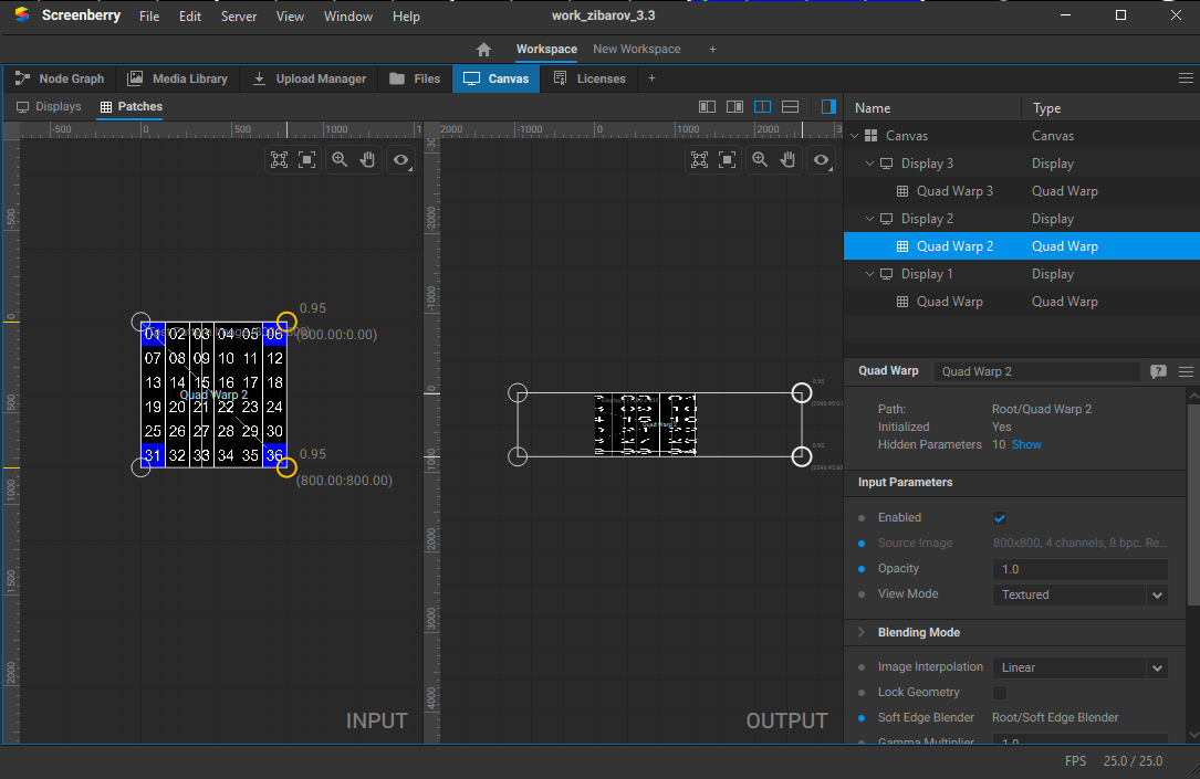
Configure patches with a 2×2 point layout.
Use the shortcut Ctrl+Shift+X to quickly reduce the number of control points.
Align the geometry (output) points:
Ensure the left/right sides are perfectly vertical.
Align the top/bottom edges to match the physical screen borders.
Align the UV (input) points to match the physical markers on your screen.
Important:
Do not move patch points outside the designated area in the Patch Editor.
Doing so will break the automatic blending process and result in visible hard edges.
6. Input vs Output Calibration Guidelines
When working with 4-point patches:
Adjust UV (input) points horizontally to correct horizontal alignment.
Adjust geometry (output) points vertically to correct vertical alignment.
To verify vertical alignment, use a laser level (green cross-line recommended) to ensure that vertical lines are not tilted.
7. Alternative Approach (Without Markers)
If you’re not using physical markers, perform a rough initial calibration.
Then, in the Test Pattern node, configure a subgrid with smaller cells in the overlapping regions.
Visually inspect the overlapping area:
If one projector’s grid cells appear wider, and the other’s narrower, UV alignment must be adjusted.
In the Patch Editor:
Select both projectors’ patches on the input side.
Choose the two right points of the left patch and the two left points of the right patch.
Move them together horizontally to shift the overall content.
Iterate this adjustment in small steps until the cell sizes visually match across projectors.
8. For Non-Flat Screens
Subdivide the grid (Ctrl + X), then proceed with calibration to account for curvature or irregularities.
9. Additional Tips
Calibrate patches strictly to match the physical screen.
If additional warping is needed for specific content, use a Render Target node with patches as a separate adjustment layer.
Perform geometric calibration using the Test Pattern grid with blending disabled.
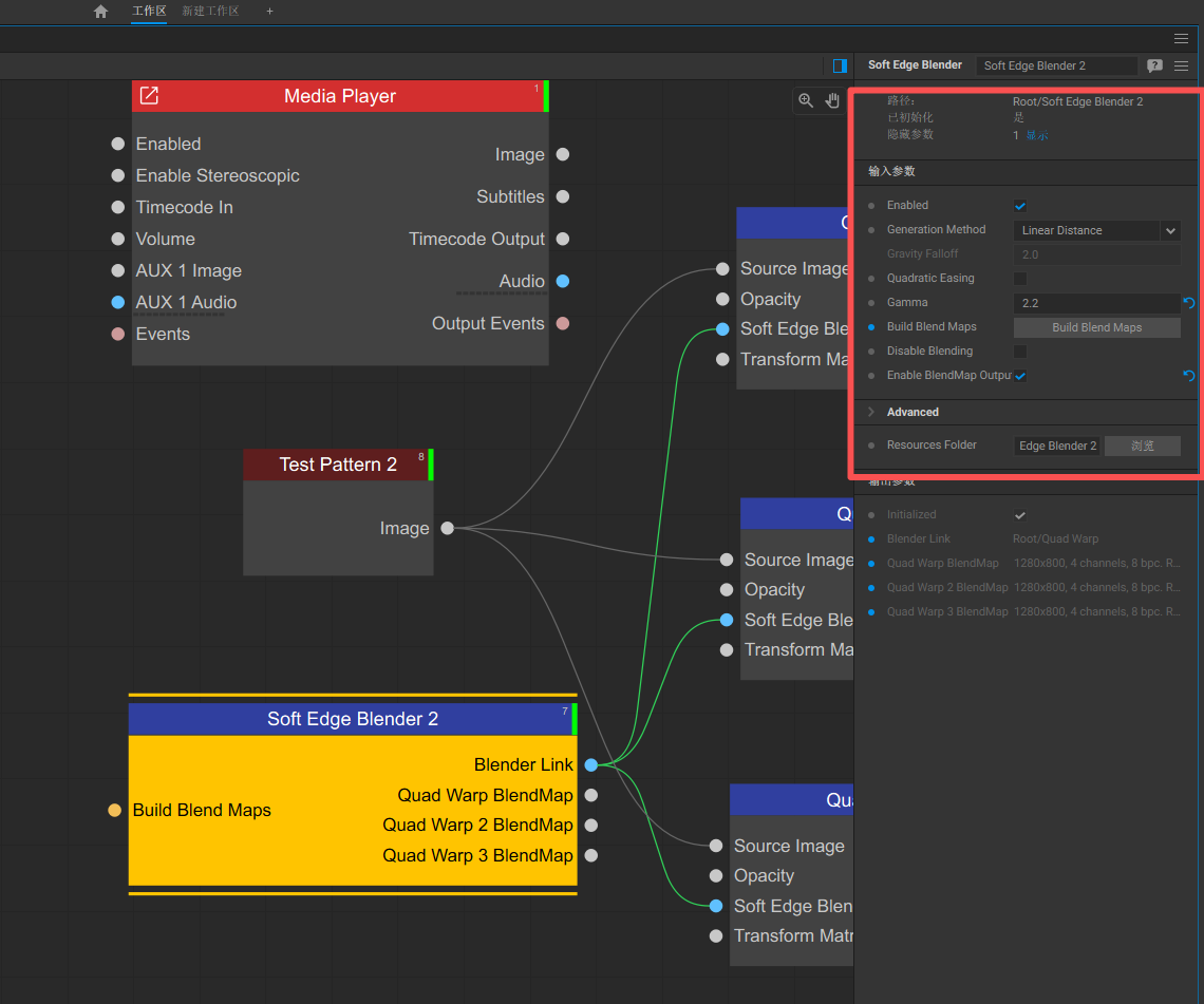
Once geometry is properly aligned, use the Soft Edge Blender to generate blending maps.
Output a white image to check the blend quality.
Fine-tune projector settings (brightness, color correction, etc.) to improve color consistency across the panorama.
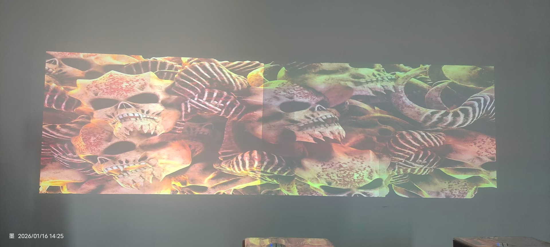
I ran into some issues. After I manually fused the projections, I noticed a very noticeable gap in the middle of the image. I haven’t figured out what caused it. How should I deal with this?
This behavior is unusual. In earlier versions, there were some known issues with the Soft Edge Blender node when using patches with control point opacity value less than 1.0. You can adjust the opacity of patch control points using the [ and ] keyboard shortcuts. However, this issue was addressed in a version prior to the current stable release, v3.3.9, so it should no longer be affecting your setup.
Here are a few things you can try:
Rebuild the blending maps in the Soft Edge Blender node.
Verify your node graph:
Make sure that both patches share the same source image.
The Soft Edge Blender relies on the UV (input) vertices of the patches to automatically calculate blending maps, so mismatched sources can cause unexpected results.
Test by disabling one display:
When a single display is disabled, you should only see light coming from the remaining projector.
On the shared edge, you should observe a gradient transitioning from full brightness (100%) to 0%, corresponding to the blending falloff.
Regarding your question on manual brightness and color correction:
You can also make adjustments directly within the Screenberry node graph:
Adjusting brightness:
You can control the brightness of patches using their opacity setting.
Color adjustments:
To modify colors via nodes, you can use the Color Correction node. However, to apply it correctly, you need to render the patch into a Render Target first.
The recommended node chain would be:
Patch → Render Target → Color Correction → Display
This approach allows you to fine-tune color and brightness on a per-patch basis directly in software, providing a flexible alternative to projector-level controls.
If you can share a screenshot of your current node graph, I can provide more targeted guidance.
I’m very sorry. I did read your previous reply that said, ‘Don’t move the control points outside,’ but I have been exploring this software on my own and I am very interested in it!
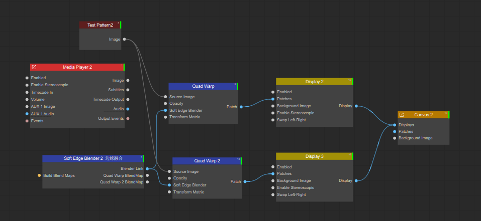
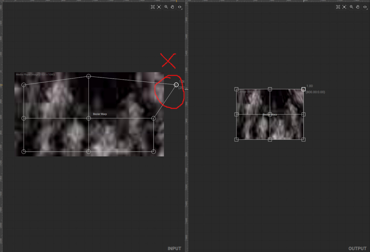
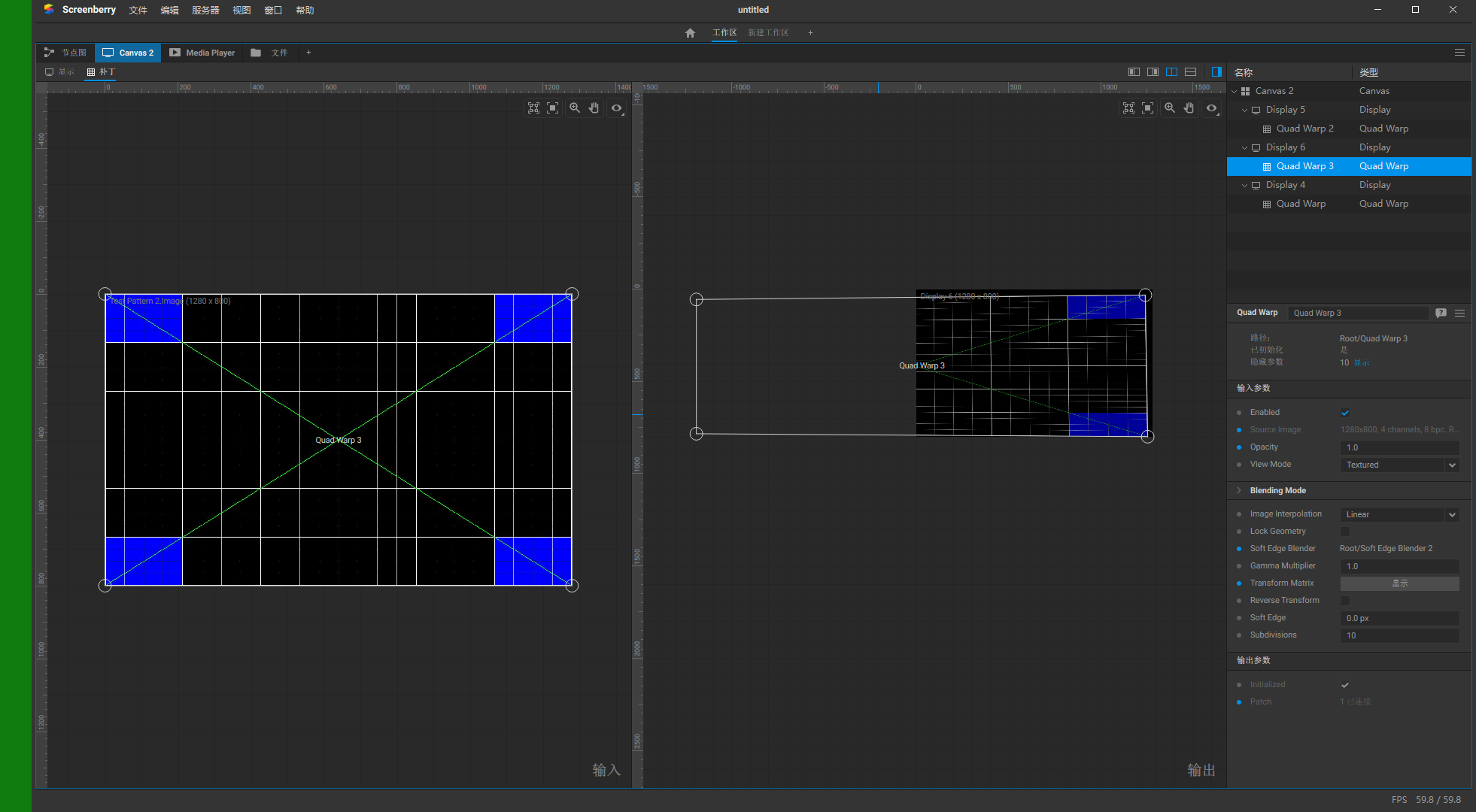
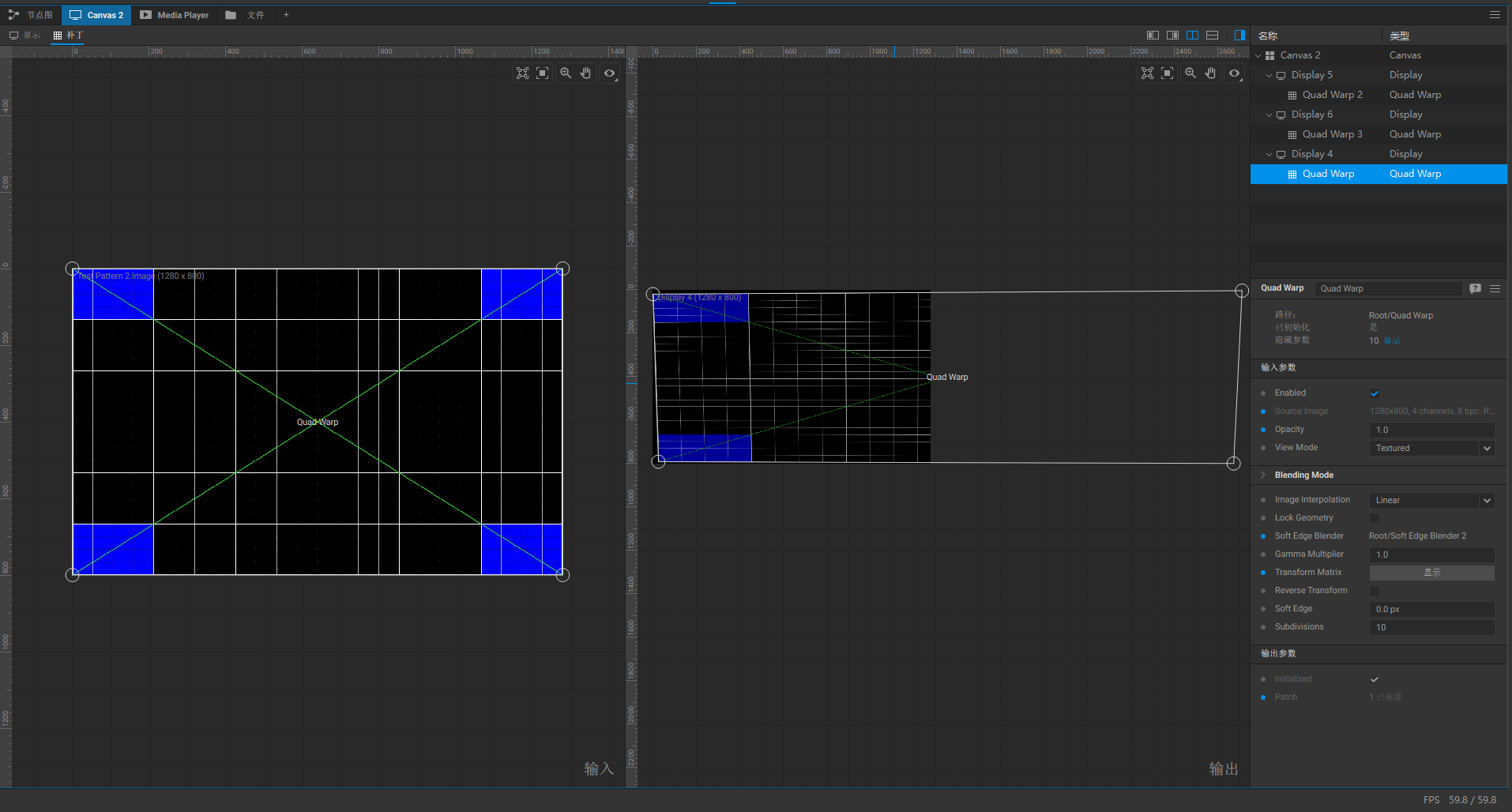
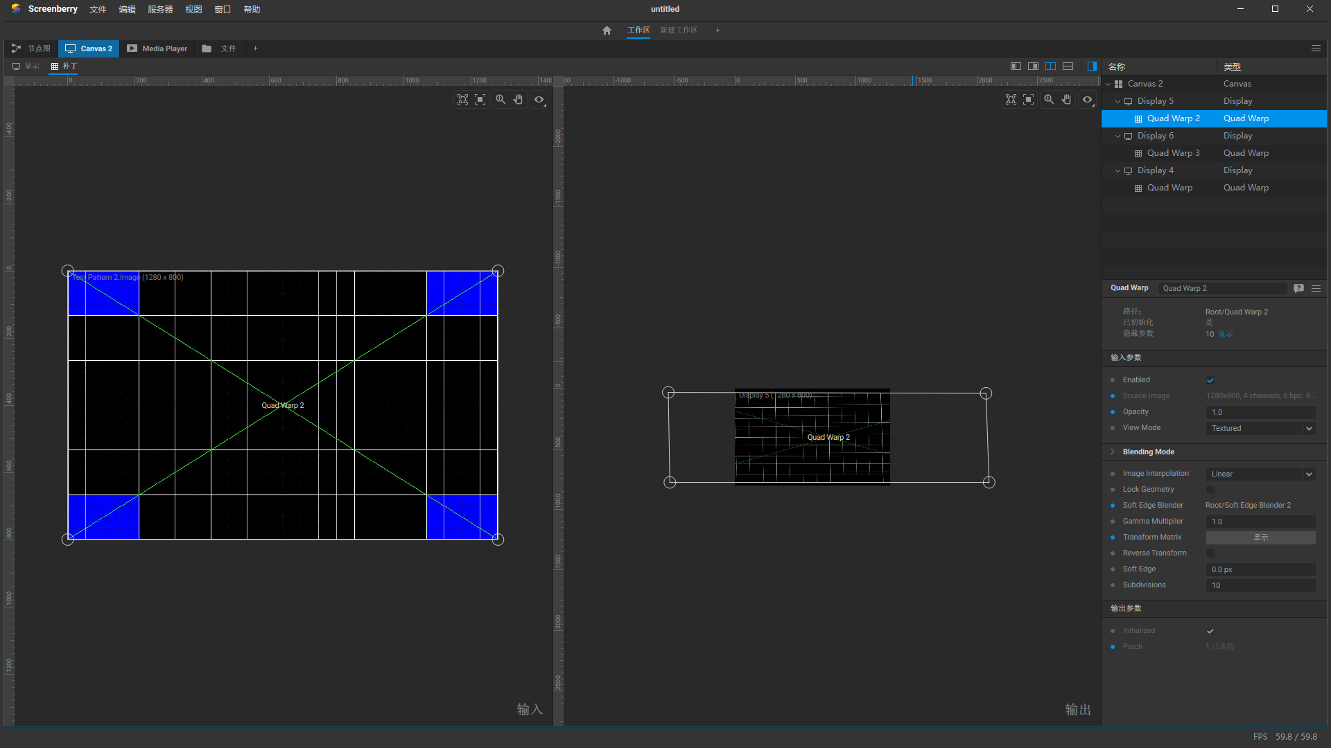
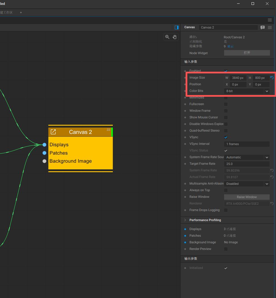
However, I don’t quite understand what you mean by ‘don’t move the control points outside.’ When I was experimenting on my own, I did move the control points of the output image outside the rectangle. I always thought it was enough to align the X in the test pattern, but in doing so, the control points would end up outside the rectangle. I will share my node graph with you as well as some of my parameter settings.
I look forward to your guidance. Thank you!
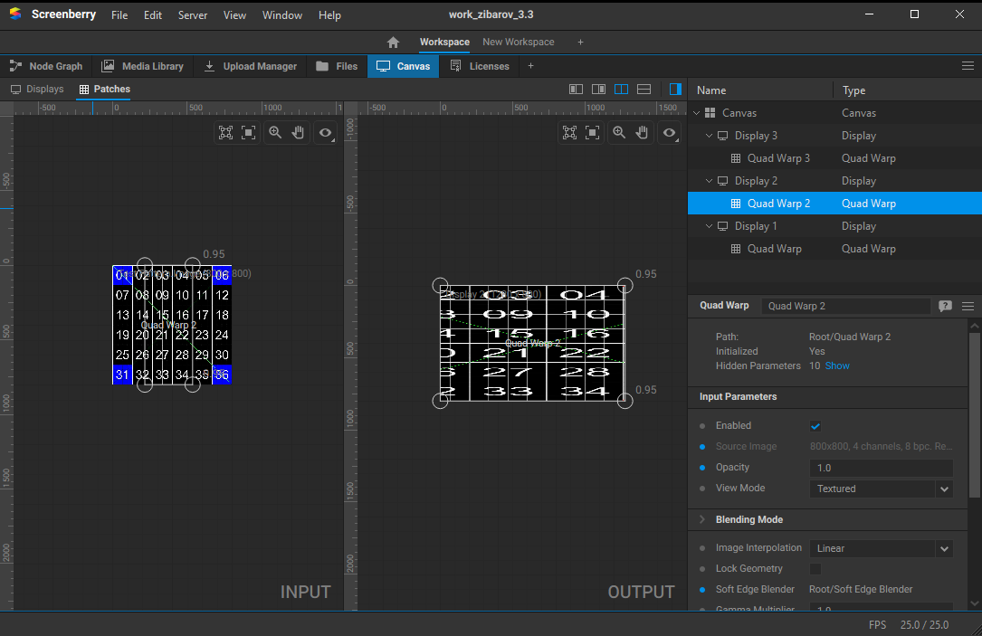
Here is my node graph and some parameter settings, and I also want to implement picture-in-picture on it. However, the PIP video is very blurry, and some dark videos are hard to see.